"The Generator"
The "brain" of the instrument
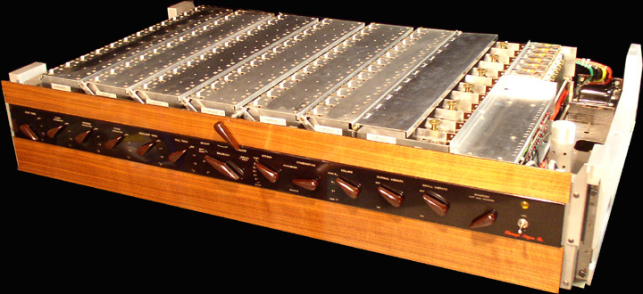
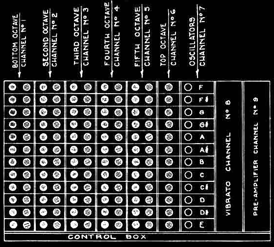
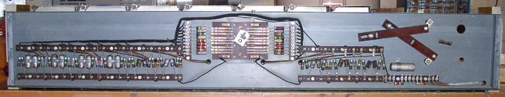
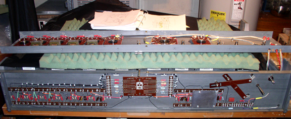
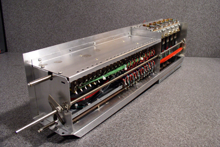
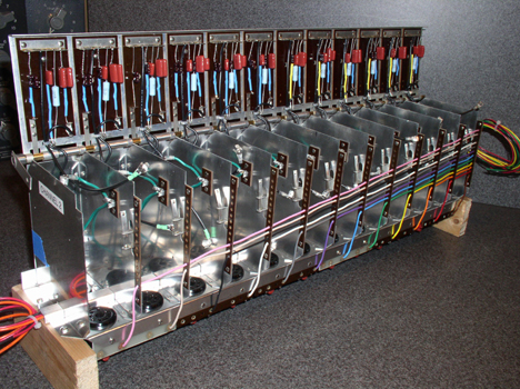
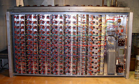
The massive "Generator" consists of the control box in the front, and channels 1 through 9 in the rear. All the audio processing in the Novachord is performed in the generator. The Control Box houses the controls for the instrument as well as all the passive audio processing circuits including the 5 resonators. Channels 1 - 9 house the active vacuum tube circuits. There are 12 oscillators, 60 frequency dividers, 60 band pass filters, 72 VCA's, a pre amp and a hex-vibrati in the generator. There are a total of 146 tubes in the generator.
The Control Box
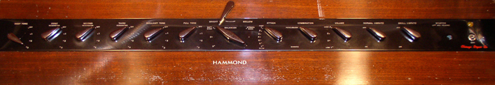
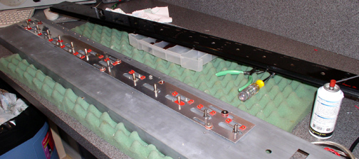
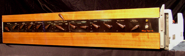
The Control Panel before restoration. The one saving grace about this particular Novachord is that the front panel is in good condition. I'm going to have the wood panels refinished, but I'm still wondering where to get the Hammond decal.
The Control Box internals before restoration - The rear section (shown above) contains the 18 channel passive mixer with it's Rube Goldberg mechanical keyboard volume balancer.
The preset mechanism - The Combination lever engages the 2 preset sounds of the Novachord. A cam that slides underneath the front panel sets all the controls to either the "Percussion" preset or the "Singing" preset. The "Percussion" preset is very close to a piano sound. The "Singing" preset is somewhat organ like.
The Resonator Filter Bank before restoration - The front section of control box (the control panel) houses the filters and the controls for the instrument. A combination of rotary switches sets the tone of the Novachord. From left to right: 1 low pass, 3 band pass, 1 high pass and 1 bypass.
|
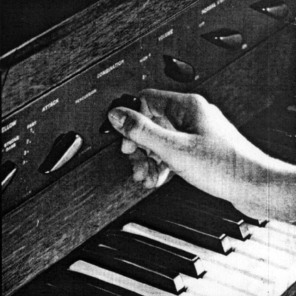

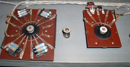
| The Attack Control - On the left half of the above photo is the attack control. A seven position switch that actually adjusts the attack, decay and sustain of all 72 notes. The release is engaged by a foot pedal. This is one of the many features of the Novachord that place it in the domain of the synthesizer. And you thought the ADSR was invented in the 60's - not true. The control on the right is the volume control. | 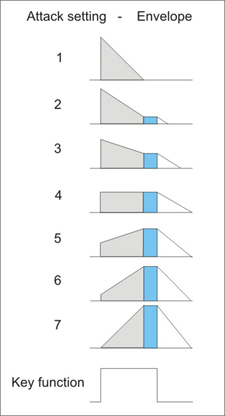 |
|||||
The Operation of the Envelope Generators is shown in the diagram on the right. The gray shaded areas are the attack and decay functions. The blue shaded area is the sustain voltage as the key is held down. The white areas are the release function engaged by the foot pedal after the key has been released. The times are not variable, but the levels are. Somewhat limited, but amazing for a pre-WW2 synthesizer. Setting 1 is for percussive type envelopes. Setting 3 looks like a typical synthesizer ADSR setting. Setting 4, without the release function is an organ envelope. Setting 7 would be great for string simulation. Please note that the release also works on setting 1 if the key is released soon enough.
|
||||||
The Control Box after restoration - I ended up replacing all the passive components. |
||||||
Restoration of the individual generator channels
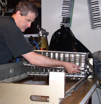
Disassembly of the Generator - Some kind of madman pulling out channel 2.
The 9 generator channels were tackled in descending order:
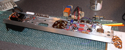
Channel 9 after restoration - The Preamplifier - gone are the nasty capacitors. There was a massive PCB oil filled capacitor in the center of this channel. But I suspect the real culprits of the contamination were the 2 "black tar" capacitors mounted alongside of the oil capacitor. The black goo that was leaking out of them was incredibly nasty. It had an awful smell and a very low boiling point. If a soldering iron got near the stuff, it started bubbling like crazy and emitting these nasty fumes. I never encountered anything like this, but I knew I didn't want it in my house. To clean the channel properly, I had to strip it to the chassis. While I was cleaning the "tar of doom" off of the chassis, I noticed it had one good quality - It polished the chassis to an almost mirror like shine. So, I polished the whole chassis with descending grades of steel wool. It looked and smelled much better. The preamplifier is a simple circuit compared to the rest of the instrument. So I knew at that point, I had a long long road ahead of me.
Channel 8 before restoration - There are 36 capacitors beneath the 3 X 12 pole switches. The wiring harnesses leading to the reeds and oscillators were composed of cotton covered wire that wreaked of PCBs. They all needed to be replaced.
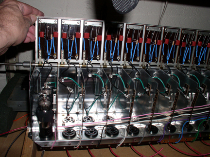
Channel 8 after restoration - The Hex Vibrati - the 6 mechanical reeds in the back housing are always wiggling.They are engaged through 3, 12 pole switches to each oscillator so that when you play a chord - each note has a different vibrato rate. Individual LFO modulation of each note - nice. The red bar starts the reeds moving manually by a lever on the front panel.
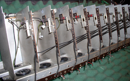
Channel 7 restored - This is the underside of the twelve oscillator circuits comprising the top octave tone generators.
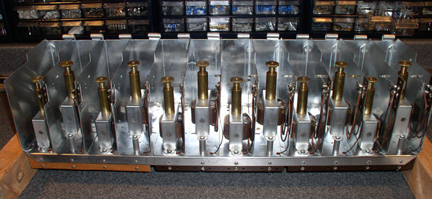
This is the top of Channel 7 after restoration - the custom transformers have adjustable cores that are used to fine tune the instrument. Each compartment in channel 7 houses a transformer, a tube and a coarse tuning capacitor.
Channel 6 after restoration - This channel houses the twelve VCA's for the top octave. The loomed wire supplies the signals from the individual envelope generators in the keyboard. At this pont, I am planning to eliminate the spring connectors and use circular multi-pin AMP connectors instead.
Channel 5 before restoration.
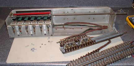
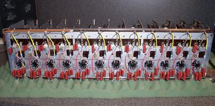
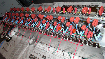
Channel 5 after restoration - Each compartment houses a frequency divider tube, a VCA tube and a passive band pass filter under the lid. The hinge of the compartment has a switch mechanism that reduces the bandwidth of each band pass filter for the "mellow" setting. The first compartment has a pair of tubes in it for show. There are 5 channels like this one in the generator, each with 12 compartments, for a total of 60 circuits. Fun fun fun!
Channel 4 before restoration - the capacitors and the large resistor mounting bar have been removed.
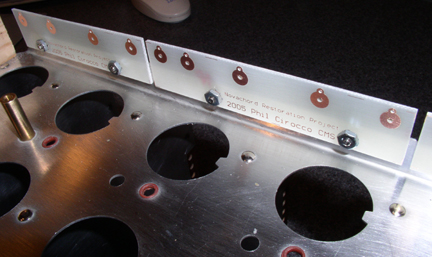
Channel 4 during restoration - Here are some of the custom PCB's I made to replace the smashed terminal strips.
Channel 4 after restoration - This is the underside showing the polypropylene film caps and the metal film resistors. Many of the capacitors had to be doubled up to get the correct value specified by the factory. Also, due to tolerance limitations, all values and combinations of values had to be selected and verified on a digital capacitance meter. The 5 divider/vca channels end up using about 150 capacitors each.
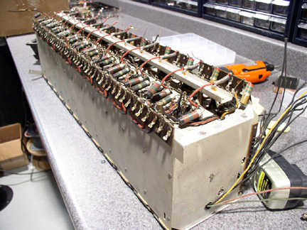
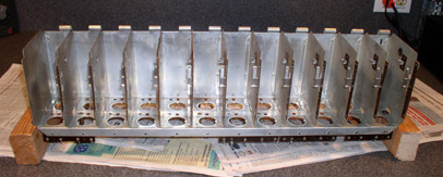
Channel 3 - during restoration - This is the chassis of channel 3 before polishing. The Novachord Restoration Project involves removing all the components, all the wiring, removing all the tube sockets, cleaning and polishing the chassis, installing the reconditioned tube sockets, installing new wiring, resistors and capacitors.
Why go this far? - The
primary reason I went so far with the cleaning, polishing and rewiring
was to protect
my
family's health.
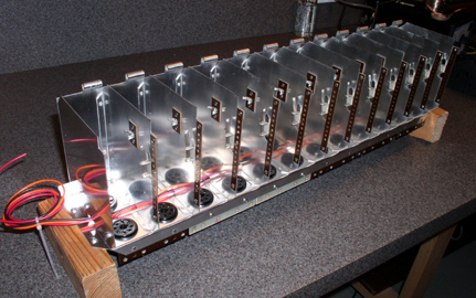
Channel 3 after polishing and wiring - A large amount of elbow grease was required.
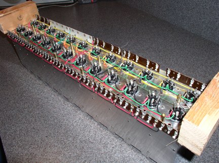
Channel 2 After restoration - A light at the end of the tunnel.
Channel 2 after restoration
Channel 1 after restoration - The next step is to paint the generator frame and assemble the generator.
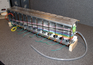
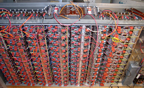
Assembling the Generator - The compartment lids are open.
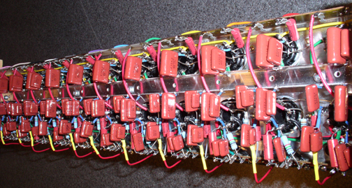
The underside of the Generator during assembly - The worst is over.
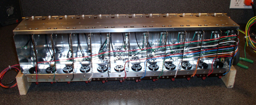
The Generator after restoration - All ready to go.
©2005 Phil Cirocco
|
||||||

Other Resources: The Novachord Sightings page is here Movie and TV listings The History of Electronic Music - a 1936 Perspective! - by Benjamin Miessner This is a beta site I am transcribing - excuse the gaffs. Links: http://www.organhouse.com/hammond_novachord.htm http://www.oldtech.com/synth/HammondNovaC1.html http://www.synthmuseum.com/hammond/hamnovachord01.html http://theatreorgans.com/hammond/novachord/ http://www.dairiki.org/HammondWiki/HammondNovachord
|
||
|
|||||||||||||||||||
|